
2.0 Objectives
- To study pneumatic circuit design principles for industrial applications.
- To simulate and verify pneumatic circuit operations using FluidSim simulation software.
- To build, test, and evaluate actual circuit operations on the Festo Pneumatic Mobile Trainer workstation.
3.0 Introduction
Pneumatic systems harness the energy of compressed air to generate mechanical force, enabling precise and repeatable motion in automated machinery. These systems are widely preferred in manufacturing environments due to their simplicity, low maintenance requirements, inherent safety in explosive atmospheres, and cost-effective operation.
Depending on the application, typical actuated motions include pushing, pulling, lifting, clamping, rotating, and holding. Unlike hydraulic systems, pneumatic actuators operate cleanly without fluid contamination risk and can achieve very high cycle speeds — making them ideal for high-throughput production lines.
Compressed-air driven pneumatic systems are found across a broad spectrum of industries, powering components such as cylinders, rotary actuators, and grippers in equipment including:
- Fabrication and stamping equipment
- Packaging and packing machinery
- Paint spraying and coating lines
- Liquid filling and dispensing equipment
- Robotic end-of-arm tooling (EOAT)
- Material handling and conveying systems
- Pneumatic presses and clamping fixtures
- Air-powered hand tools and torque wrenches
- Medical and pharmaceutical processing equipment
- Food-grade processing and packaging lines
A typical pneumatic circuit consists of a compressor (air supply source), a Filter-Regulator-Lubricator (FRL) unit for air conditioning, directional control valves (DCVs) to route airflow, actuators (cylinders or motors), and flow control valves to regulate speed. Understanding how these components interact is fundamental to designing reliable automated systems.
4.0 Pneumatic Symbols for the Equipment Set
Standard pneumatic symbols — defined by ISO 1219-1 — are used throughout this lab to represent components in circuit diagrams. Familiarise yourself with the symbols for the components available in the Festo mobile trainer kit before commencing the experiments.
Reference: Refer to the Festo Pneumatic Trainer Component List and the FluidSim symbol library for the complete set of pneumatic symbols used in this laboratory. Key symbols include single- and double-acting cylinders, 3/2 and 5/2 directional control valves (spring return and detent types), roller lever valves, one-way flow control valves, time-delay valves, shuttle valves (OR elements), pressure regulators with gauges, and the air service unit (FRL).
5.0 Apparatus
A pneumatic circuit is used to automate the operation of an industrial sliding door — a common application in clean rooms, warehouses, and logistics facilities. The system must allow the door to be opened or closed from both the inside and outside (bi-directional manual control), and the travel speed in both directions must be independently adjustable to prevent slamming and protect personnel and goods.
This is typically achieved using a double-acting cylinder controlled by a 5/2 double pilot-actuated directional control valve, with one-way flow control (meter-out) valves on each actuator port for speed regulation. Push-button or roller lever valves on either side of the door act as the pilot signals.
A diagram of the components is shown in Figure 1, with some of the piping connections missing. Study the layout and complete the circuit.
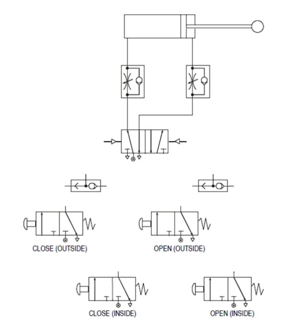
- Complete the piping connections in the circuit diagram shown in Figure 1.
- Build and test the completed circuit in FluidSim simulation software.
- Name all components used in the circuit and state their function.
- Identify and explain the type of control strategy used in this circuit (e.g., direct, indirect, or pilot-operated control).
- Describe the step-by-step operation of the door — both the opening and closing sequences — with reference to valve states and cylinder movement.
Sequential control is a fundamental technique in industrial automation where two or more actuators must execute a series of actions in a defined, repeatable order. Each step in the sequence is triggered by a signal confirming the completion of the previous step — this is known as dependent sequencing or cascade control.
In this experiment, a heat treatment production line is automated. Metal workpieces are loaded into a furnace using two pneumatic cylinders working in sequence: one cylinder opens the furnace door, and a second cylinder pushes the metal block into the furnace. The system is initiated by an operator via a push-button start, and the sequence is fully interlocked to prevent simultaneous actuation.
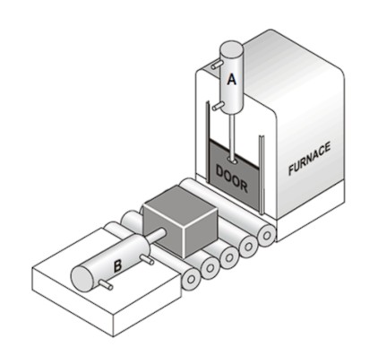
Sequence of Operations:
- The operator activates the push-button start signal to initiate the cycle.
- Cylinder 1A (furnace door cylinder) extends, opening the furnace door fully.
- Cylinder 2A (loading cylinder) extends, pushing the metal block into the furnace.
- Cylinder 2A retracts (instrokes) back to the home position.
- Cylinder 1A retracts, closing the furnace door. The cycle is complete.
The pneumatic circuit that implements this sequential operation is shown in Figure 3 below.
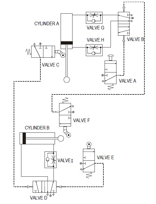
- Build and test the circuit in FluidSim simulation software, verifying the correct sequence of operations.
- List all components used in the circuit and describe their roles.
- Provide a detailed step-by-step explanation of the circuit operation, referencing each valve actuation and cylinder motion in sequence.
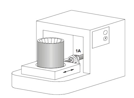
In paint manufacturing, freshly poured multi-colour liquid paints must be thoroughly blended after being combined in a bucket. A pneumatic vibrating machine achieves this by rapidly oscillating a double-acting cylinder (1A) in a back-and-forth motion within a defined stroke range — producing a shaking action that homogeneously mixes the pigments.
When the push-button is pressed, the initially extended cylinder 1A retracts fully and then enters an oscillating mode within the retracted end-stroke zone. The oscillation is bounded between the fully retracted position (controlled by Roller Lever Valve RLV1) and a mid-stroke central position (controlled by Roller Lever Valve RLV2). A pressure regulator governs the air supply rate, which determines the oscillation frequency. Set operating pressure: p = 400 kPa.
After a set vibration time of t = 5 seconds (controlled by a time-delay valve), the oscillation ceases, and the cylinder extends fully to its forward end position, where it actuates RLV3 — confirming cycle completion and resetting the system.
- Design a complete pneumatic circuit for the paint bucket vibrator based on the description above.
- Build and test the circuit on the pneumatic mobile workstation, verifying oscillation behaviour and time-delay cut-off.
- List all components used and state their specific function within the circuit.
- Draw and explain the displacement-step diagram (step-motion diagram) for cylinder 1A, clearly indicating the oscillation phase and the final extension step.
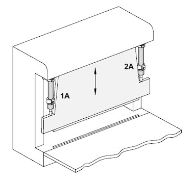
Thermoplastic welding is a process used to permanently join plastic sheets by applying heat and pressure. In this pneumatic application, two double-acting cylinders — (1A) and (2A) — simultaneously advance to press two electrically heated bars together, bonding two thermoplastic sheets by heat fusion welding (refer to Figure 5). The system is designed for sheet thicknesses ranging from 1.5 mm to 4 mm, and the weld seam can be of any length.
The clamping force of both cylinders is precisely controlled via a pressure regulator set to p = 400 kPa. Pressure gauges are installed between each cylinder and its associated one-way flow control valve to assist in monitoring and adjusting applied force. The cylinders advance in parallel with exhaust air throttled (meter-out control) to ensure smooth, controlled progression.
Upon reaching the welding end position — confirmed by limit sensors — the bars remain pressed for a dwell time of t = 1.5 seconds (controlled by a time-delay valve) to ensure proper bonding. The cylinders then retract simultaneously to the home position. An emergency push-button is also provided to initiate an immediate return stroke at any point during the cycle.
- Design the pneumatic circuit for the thermoplastic welding machine based on the specifications described.
- Build and test the circuit on the pneumatic mobile workstation, verifying parallel actuation, pressure setting, and time-delay retraction.
- List all components used and explain their function in the circuit.
- Draw and explain the displacement-step diagram (step-motion diagram) for both cylinders 1A and 2A, showing the parallel advance, dwell, and simultaneous retraction phases.
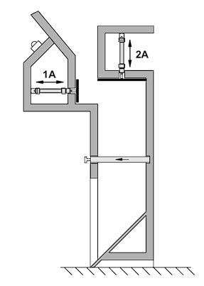
7.0 Exercise: Pneumatic Compactor for Domestic Rubbish
★ Design ChallengeA prototype pneumatic domestic refuse compactor (under-table model) is to be designed and tested. The system operates at a maximum working pressure of P = 300 kPa and uses two pneumatic cylinders:
- Pre-compactor (1A) — equipped with an integrated glass crusher for pre-processing of refuse before main compaction.
- Main compactor (2A) — delivers a maximum compaction force of F = 2,200 N to compress the refuse volume.
The positional sketch (Figure 6) illustrates the physical arrangement of both cylinders within the compactor housing, and the time-motion diagram (Figure 7) shows the intended timing relationship between the two actuators. Note that the time lag t represents an inherent system delay during the return stroke of the main compactor (2A), which must be accounted for in the circuit design.
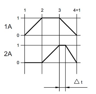
Based on the positional sketch and time-motion diagram, design a complete pneumatic circuit for the domestic refuse compactor. Present your circuit design using FluidSim simulation software, and ensure the displacement-step diagram accurately matches the time-motion diagram provided in Figure 7.
8.0 Recommendation
Critically evaluate the pneumatic systems studied in this laboratory. Identify limitations or inefficiencies observed during testing and propose concrete improvements or modifications to enhance performance, reliability, or energy efficiency. Consider aspects such as:
- Substitution of mechanical pilot signals with electronic sensors (e.g., proximity switches or reed switches) for a more robust electro-pneumatic implementation.
- Integration of proportional pressure regulators or servo pneumatic valves for finer force and speed control.
- Introducing a Programmable Logic Controller (PLC) to replace pure pneumatic sequencing, improving flexibility and ease of reprogramming.
- Energy saving measures such as pressure zoning, exhaust air recovery, or using smaller-bore cylinders where appropriate.
Additionally, document all relevant safety and health considerations for conducting this laboratory, including: safe working pressure limits, proper hose and fitting checks before pressurising circuits, personal protective equipment (PPE) requirements, emergency stop procedures, and correct handling of glass crusher elements in Experiment 7.
9.0 References
List all references consulted during the completion of this lab report. Use an appropriate academic citation format (e.g., IEEE or APA). References should include any textbooks, Festo documentation, FluidSim user guides, technical standards (e.g., ISO 1219-1 for pneumatic symbols), and any online resources used.